Surface Geophysical Methods for Groundwater Prospecting
Doria L. Kutrubes, M.Sc., P.G.
Ms. Kutrubes covers an overview of different near surface geophysical methods used in groundwater prospecting, a methodology on the design of a water prospection survey, and highlights lessons learned from case studies. The following surface geophysical methods are discussed:
A. Ground Penetrating Radar (GPR)
B. VLF and other EM Methods
C. Electric Resistivity Tomography (ERT)
D. Gravity
E. Seismic Refraction/Tomography (SRT)
F. Seismo-Electric Method
G. Magnetometry
The Q&A portion addresses additional topics (click here).
Surface Geophysical Methods for Groundwater Prospecting
In this video, Kutrubes presents the outline for the webinar. The aim is to show that these surface geophysical methods can be used to evaluate environmental impact on potable water supplies and the reduction of water recharge of aquifer systems.
The Q&A portion addresses additional concerns from the participants.
A. Ground Penetrating Radar (GPR)
GPR operates via high frequency EM waves (>10 MHz) to characterize the soil subsurface. GPR is capable of investigative depths of a few meters to tens of meters, and measures the difference in the complex dielectric permittivity or Relative Dielectric Permittivity (RDP using the Bruggeman Hania Sen (BHS) model.
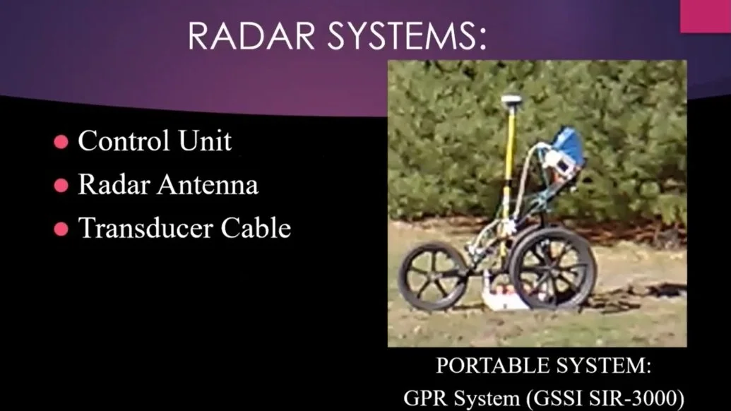
GPR systems consist of a control unit, radar antenna, and transducer cable.
Also covered are:
Four major sources of GPR signal losses
GPR uses and its applications
B. Very Low Frequency (VLF) and other EM Methods
VLF, with 10s kHz range, generates in-phase and quadrature responses with the highest response occurring at a fracture. VLF delineates water/mineral-bearing fractures to depths of about 30 m. It only detects fractures that are in the same direction as the transponding station, and its measurement lines must be orthogonal to fractures.
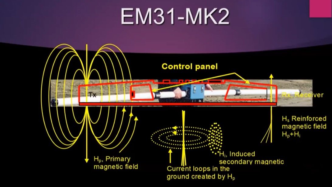
Electromagnetic Coupling Instruments, such as EM-31 and EM-34 , measure the apparent average conductivity of one or more ground layers to a certain depth. This depth depends on the coil spacing, orientation, operating frequency, and the medium below ground. In vertical dipole mode, coils are insensitive to near-surface variations with deeper detection depths. As a rule-of-thumb, depth in vertical dipole mode is twice as long as in the horizontal dipole mode.
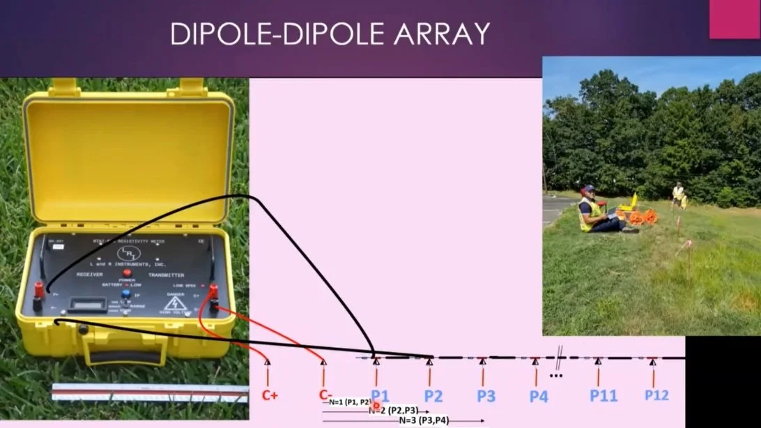
C. Electrical Resistivity Tomography (ERT)
ERT is based on the principle of Ohm’s law and measures an apparent electrical resistivity in Ohm-meters.
ERT array types can be Wenner, Schlumberger, Dipole-Dipole, Pole-Dipole, and Twin-Probe. The Wenner array is for engineering surveys and corrosive studies. Dipole-Dipole array is for groundwater investigations. The Twin-Probe array is for archeological investigations.
Tomographic images, which are produced by INVRES2D / INVRES3D, can reveal weathered or soil bedrock, and fractured zones.

DEF. Gravity - Seismic-Refraction/Tomography - Seismo-Electric Method
D. Gravity
Gravity method is based on Newton’s Gravitational Law where the perturbational field is evaluated to localize the small anomalies in the regional gravitational field. The LaCoste and Lumberg gravity meter is used to measure and deduce these gravitational field anomalies.
A standard workflow of gravity is described to determine the Complete Bouguer Anomaly (CBA), which can be calculated using Gravity Tomographic Inversion software.
E. Seismic Refraction/Tomography (SRT)
SRT is performed using an M-channel seismograph and listening devices called geophones in a line away from a signal source. The source, which can be a hammer or explosives, generates a sound wave that is picked up by the geophones. The rate at which the sound reaches the geophones is proportional to the layers’ velocity.
F. The Seismo-Electric Method
Like SRT, Seismo-electric uses four electrodes where apparent resistivity between them is measured, and the geophones measure the acoustic wave arrivals. It is based on the streaming potential given by the Helmholtz-Smoluchowski equation. The Seismoelectric method is effective in groundwater prospecting and finding bedrock structures hundreds of meters deep, and highly effective in locating geothermal sources.
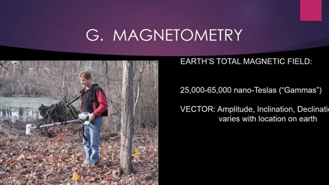
G. Magnetometry
Magnetometry to measure the Earth’s total magnetic field is not typically used for water survey but can be used to define the bedrock lithologies or a fault in the bedrock. This method looks for perturbations in the regional magnetic field strengths in hundred nano-Tesla. World magnetic maps of magnetic field strengths, given in several thousand nano-Tesla, are available.
Examples of magnetometry maps used to identify different types of bedrock include pre-metamorphic faults with surrounding material having high-temperature and high-pressure iron oxide (i.e. puritate, which is magnetic), and pyriate (non- or low-magnetic) to locate the fault zone by simply mapping the two metamorphic grades.
Design of a Water Prospection Survey
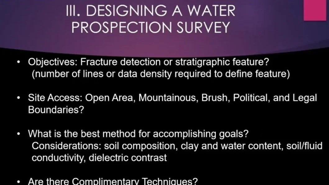
In designing a Water Prospection Survey, follow these general guidelines:
Clearly state the objective for the detection of a fracture or an unconfined aquifer.
Determine the site access insofar as open area, mountainous, brushy, hilly, etc. and its legal boundaries.
Select one or multi- prospection methods based on soil composition, clay and water content, soil/fluid conductivity, and dielectric contrast.
Additional instructions and recommendations for equipment are given for the GPR method, VLF method, ERT method, gravity method, and SRT method.
Case History
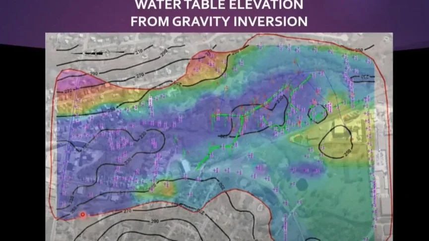
Kutrubes describes a case history of groundwater supply in unconsolidated material using Gravity and GPR to expand the municipality water supply by locating maximum saturated thickness, and thus optimization of well placement. She explains the advantage of using gravity inversion in combination with GPR, and certain limitations of other geophysical methods.